BATTLE SHIFTER HONDA RS125 1995/2004 FITTING INSTRUCTIONS
Please 'Refresh' this page every time you visit. If it is slow to reload, you know then that this page has been updated since your last visit.
BATTLE SHIFTER HONDA RS125 1995/2019 FITTING INSTRUCTIONS
The Battle Shifter by Battle Factory is a lightweight, compact semi-automatic upshifting system that provides quick, smooth shifts every time.
Unlike other popular shifters, the Battle Shifter works by automatically adjusting the duration of the ignition cut to match RPM’s – longer cuts at low RPM’s and shorter ones at high RPM’s.
Whereas other shifter setups simply act as a switch that cut power completely, the Battle Shifter reduces current to the ignition coil to stop spark.
This ensures that juice keeps flowing to your gauges, eliminating annoying readout flashes and reducing overall system shock to provide the smoothest shift possible.
The Battle Shifter automatically cuts out under 3,000 RPM’s to prevent engine stall during slow speeds and idle and comes fully setup for your bike from the factory eliminating the need to adjust the length of the ignition cut.
Your Battle Shifter comes with:
Battle Shifter control unit.................................................. x 1
Pull switch set................................................................... x 1
Zip straps 250 mm (for attaching the unit)..................... x 2
Rubber sponge................................................................. x 1
Connector ......................................................................... x 1
Large sticker .................................................................... x 1
Special adjustment screwdriver ..................................... x 1
IMPORTANT:
To ensure the long life of your unit, please read all instructions carefully.
Check that the adjustment window is covered before riding!!
Take care to ensure that all wires are connected correctly, especially the <+> and <–> as incorrect installation can result in damage to the unit.
Be sure to ground the shifter’s <–> (black wire) to the frame.
Avoid installing the control unit in places where it will be exposed to excessive water, heat, dust or vibration.
Also avoid securing it the close proximity of the ignition coil or plugs as electronic noise could interfere with normal operation.
We recommend installing it in a convenient spot near the CDI on the meter stay.
Be sure to insert the included sponge under the control unit before securing with the provided zip straps.
INSTALLATION:
Please refer to the wiring diagram in your owner’s manual.
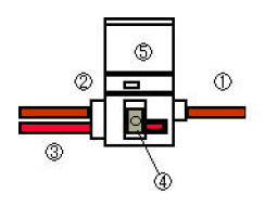
RED LEAD WIRE: This becomes the Battle Shifter’s 12-Volt power source.
Locate the three lead wires coming out of the back of the tachometer.
Use the connector provided to connect with the black lead wire (For instructions on how to use the connector see the following page).
BLACK LEAD WIRE: This is the unit’s ground. Secure with one of the 6 mm bolts on the meter stay.
BLUE/ WHITE LEAD WIRES: Switch with the ignition coil leads after preparing them as per the following diagram.
Cut the black/yellow lead that runs to the CDI unit close to the meter stay.
Strip some of the wire case and attach the provided connector, female end on the CDI side and male end on the side running to the coil.
Insert the blue lead wire from the shifter into the female connector and connect the white lead with the male end.
IMPORTANT: Check to make sure that all the connectors are fastened tightly and that <+> and <-> connections are correct.
Reversing <+> and <-> connections can lead to internal damage of the shifter.
CONNECTOR DIRECTIONS:
(1) <+>12 volt lead from bike: Insert into the groove of the connector.
(2) Cap: Secure wire with cap.
(3) Red lead wire from the shifter: Insert into the hole of the connector.
(4) Metal tab: Compress the metal tab with pliers to secure ? and ? .
(5) Connector cap: Close the cap and you’re done.
FINE TUNING:
Your Battle Shifter unit comes preset from the factory for optimal performance with your machine.
However, if you absolutely feel that your unit does not shift smoothly, you can manually fine-tune it with the provided screwdriver:
Peel the tape up on the side of the unit covering the adjustment window.
Adjust the volume (ignition cut time) to ensure a smooth shift with no shock when upshifting:
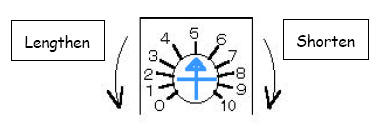
- rotate left to lengthen the ignition cut
- rotate right to shorten the ignition cut
To differentiate between when the ignition cut is long and short, use the following guidelines:
- LONG: Bike pitches and/ or speed drops when changing gears. Shift is smooth.
- SHORT: Noticeable shock when changing gears. Can’t get into gear at high RPM’s. Shift action feels stiff.
IMPORTANT: Be sure to reseal the tape over the adjustment window before riding.
TROUBLESHOOTING:
1. The shifter does not cut the ignition when up-shifting.
- Engine RPM’s are below 3,000. The Battle Shifter automatically ceases to operate under 3,000 RPM’s.
- The wires are connected improperly. Check to make sure all <+> and <-> wires are correctly connected.
- The rider may be resting foot on gear lever between shifts and this does not allow the shifter switch to re-set, ready for next shift.
2. The engine refuses to rev up into high RPM’s.
- When the control unit is installed in a place with lots of vibration, the vibration may cause the internal relay to trip and act as a limiter.
- Re-install the unit in a place with less vibration.
- Make sure that the rubber pad is inserted between the unit and installation surface.
3. The bike shifts fine at low RPM’s, but refuses to go into gear at high RPM’s.
- The ignition cut at high RPM’s is too short. Return the fine-tuning volume control (left) on the unit ever so slightly.
SPECIFICATIONS: Voltage 9V – 14V
Power Consumption In Rest 12mA (12V)
In Use 37mA (12V)
Measurements 40 x 20 x 55 mm
Manufactured by: BATTLE FACTORY
Exports of all parts supplied outside of UK, to EU Countries, USA, Australia, South Africa, Asia etc are exempt from UK VAT and will be charged 0% VAT.
On arrival to your destination country, you may be asked to pay additional duties and taxes by customs, before the shipment is delivered.
Import tax, customs & duties regulations vary from country to country.
Payment of all Import tax, customs & duties charges are the responsibility of the customer.
SP125 Limited
22 Walker Wood, Baildon, Shipley, West Yorkshire, BD17 5BE, England
Telephone 01274 583231 [email protected] Mobile 07738 626165
22 Walker Wood, Baildon, Shipley, West Yorkshire, BD17 5BE, England
Telephone 01274 583231 [email protected] Mobile 07738 626165

SP125 Limited Disclaimer
Honda, HRC and all other parts supplied by the SP125 Limited are not guaranteed when used in competition events.
As such, it is a condition of our making all parts available that it is solely the decision of each individual, rider, team member or
team whether they choose to use any part supplied and in doing so, absolve the manufacturer and SP125 Limited of any or all
such claims, including damage to equipment and/or injury to personnel irrespective of how caused.
All parts remain property of SP125 Limited until paid for in full.
All 'special order' parts, that are ordered specially under the instruction of the customer, are non returnable and non refundable.
