Replacement for the HRC Detonation Sensor Lead
Please 'Refresh' this page every time you visit. If it is slow to reload, you know then that this page has been updated since your last visit.
Replacement for the HRC Detonation Sensor Lead
for HONDA RS125/ RS250 HRC Detonation Counter & Data Logger
This system is optimized for Honda RS125 / RS250
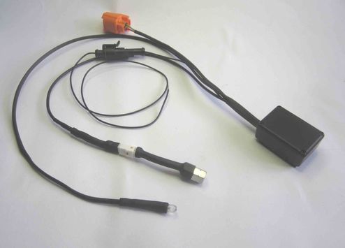
The unit provides a replacement detonation sensor for the HRC logger or HRC detonation counter and upgrades the system to add a blue flash indicator.
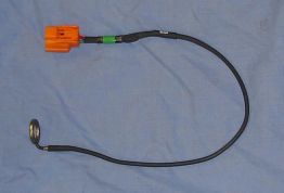
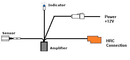
Plug the Orange connector into the counter or logger connection loom, replacing the existing sensor.
Wire the black wire into the black wire feeding the HRC unit.
Feed the indicator up to the dash foam, drill a 3mm hole in the foam and push the indicator through to face the rider.
Price : £215.00+vat
Installation Procedure for the M6/M8 stud detector
The mounting position should be on the head studs. The sensor should be tightened to the normal head nut tightness.
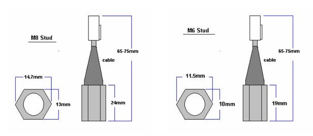
RS125 for the 5 stud head use the M8 sensor, 6 stud head use the M6 sensor
RS250 for the 7 stud head use the M6 sensor
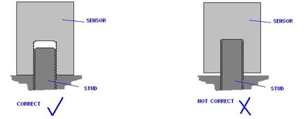
The sensors outside metal surface must make contact to the head or block or steel washer or nut. The inside surface should not touch the top of the stud. The contact of the sensor should be of high quality and clean to ensure the resonance coupling. The whole of the sensors metal surface needs to be in level contact.
M6 sensor: the detector has a maximum of 6mm of internal threads.
M8 sensor: the detector has a maximum of 8mm of internal threads.
If the threads are too long for the senor use a spacer nut or single washer
Only use a single copper washer between the head and the detector if the washer is required for the water seal such as on the standard head.
On powering up the unit will generate a detonation signal and/or flash the indicator this is normal and provides a test for the power and indicator
The detector amplifier unit must be mounted at least 80mm away from the ignition coils.
Also route all detector cables away from HT leads or the coil.
Sensitivity Adjustment
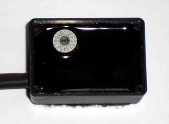
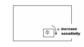
The sensitivity adjustment is by a 15 position switch; 0 is the most sensitive and F is the least.
The sensitivity adjustment is by a 15 position switch; 0 is the most sensitive and F is the least.
Set the sensitivity at the most sensitive = 0. This may show a continuous blue indication while running the engine in normal conditions. Then with the engine running slightly rich, reduce the sensitivity (go towards F) until the light never flashes under load with the RPM in the power band.
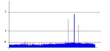
A typical detonation signal is shown below. If the unit is too sensitive then engine noise will be detected (shown as X), the unit needs to be set higher than that level. The range that detonation is detectable is wide (level Y).
A typical detonation signal is shown below. If the unit is too sensitive then engine noise will be detected (shown as X), the unit needs to be set higher than that level. The range that detonation is detectable is wide (level Y).
If the sensitivity is still too high then please contact the office as a suitable washer placed between the cylinder head or block with reduce the detection sensitivity
Leaded Fuel
Please Note; leaded fuel does not detonate as easily at unleaded fuels, the point of increased detonation on leaded fuel will be much leaner than the optimal fuel setting. The setting of the detonation unit will therefore be affected.
Excessive Detonation count
. The effect that the sensor detects can also be caused by mechanical bangs. Worn bearings in the crank or con rod can easily slap against the cylinder head when a higher revs.
. Interference can also cause the detector amplifier to detect non existent detonation, the cables and amplifier must be mounted away from the HT coil, HT wire or the LT coil drive wiring.
. Mid throttle (on the Needle / lean needle) detonation can cause actual detonation to occur that is not damaging to the piston but is still a detonation and will still be detected / counted.
Specifications:
Detector amplifier
Voltage range 9V to 20V
Input Current 5mA nominal 20mA peak
Sensor temperature range -10degC to +130degC
Amplifier temperature range -10degC to +60degC
Weight Approx 100g
Detonation output -40V 1mA 16uS
Led / Logger output +5V 5mA 200mS
Voltage range 9V to 20V
Input Current 5mA nominal 20mA peak
Sensor temperature range -10degC to +130degC
Amplifier temperature range -10degC to +60degC
Weight Approx 100g
Detonation output -40V 1mA 16uS
Led / Logger output +5V 5mA 200mS
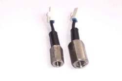
M6 and M8 Stud detectors
Exports of all parts supplied outside of UK, to EU Countries, USA, Australia, South Africa, Asia etc are exempt from UK VAT and will be charged 0% VAT.
On arrival to your destination country, you may be asked to pay additional duties and taxes by customs, before the shipment is delivered.
Import tax, customs & duties regulations vary from country to country.
Payment of all Import tax, customs & duties charges are the responsibility of the customer.
SP125 Limited
22 Walker Wood, Baildon, Shipley, West Yorkshire, BD17 5BE, England
Telephone 01274 583231 [email protected] Mobile 07738 626165
22 Walker Wood, Baildon, Shipley, West Yorkshire, BD17 5BE, England
Telephone 01274 583231 [email protected] Mobile 07738 626165
SP125 Limited Disclaimer
Honda, HRC and all other parts supplied by the SP125 Limited are not guaranteed when used in competition events.
As such, it is a condition of our making all parts available that it is solely the decision of each individual, rider, team member or
team whether they choose to use any part supplied and in doing so, absolve the manufacturer and SP125 Limited of any or all
such claims, including damage to equipment and/or injury to personnel irrespective of how caused.
All parts remain property of SP125 Limited until paid for in full.
All 'special order' parts, that are ordered specially under the instruction of the customer, are non returnable and non refundable.
