HRC DATALOGGER + DETONATION COUNTER
Please 'Refresh' this page every time you visit. If it is slow to reload, you know then that this page has been updated since your last visit.
HRC are proud to announce their new DataLogging system.
What has been used by the factory race teams is now available for the RS125 and RS250 Racing Machines.
Continuing to raise the level of competition, HRC answers the call of riders looking for a way to record faster lap times.
Developed from years of racing know how, HRC is proud to release data logger race kits for the RS125R/ 250R.
The data logger provides detailed information for setting up your machine to meet all kinds of race situations.
Simply plug it into your computer's USB to get a look at your riding style on screen. The features include:
Detonation*
(*only possible when Detonation Counter is fitted.)
RPM
Front Wheel Speed
Throttle Position
Four more channels (voltage of 0-5V)
A good use for the extra channels would be for the analysis of Front & Rear Suspension stroke movements.
All of these features are shown in graph form, which you will be able to analyse through your laptop computer.
A CD is supplied where you will need Windows98, Me, and 2000.
CPU: Pentium 200Mhz/Pentium II 266Mhz.
A 12V feed is needed from the bike which will be generated by the A.C.G.
25MB of memory is required.
A Japanese/English Manual/Parts List is available.
Optional Extras:
Manual/Parts List
Shift Light
Detonation Light*
(*only possible when Detonation Counter is fitted.)
Panel Meter (125 only)
All parts contained within the kit do have individual part numbers.
In the event of needing replacement parts, ordering these will be possible.
Please see below for a picture of the kit.
The HRC Data Analyzer Software allows you to look at your riding from many angles as well as analyze and study the condition of your machine at each point.
You can also easily map your data against another rider's.
Used with HRC's Detonation Counter for the RS125R/ 250R (sold separately),
you can eliminate carburettor setting errors and shorten overall machine setup time.
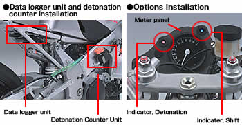
One of the main benefits is this, when coupled with the HRC Detonation Counter, is that you will be able to see where detonations occur on the circuit, in which gear position used and at what throttle position opening.
HRC's Data Logger is sure to bring the joy of victory to riders competing in all types of categories.
Main Features:
• Easy to install bolt on kit
• Windows HRC Data Analyzer Software •*Compatible OS: Windows 98/Me/2000, Japanese or English versions
•(Select English or Japanese when installing). • Detailed detonation mapping (HRC Detonation Counter with output plug required - RS125R/250 only)
• 4MB of memory provides many hours of data acquisition • Further optional parts scheduled for release will continue to add
PRICE LIST
06300-NKZ-010 DATALOGGER SET RS125 £1,150.00 + VAT Discontinued - Sold Out
06300-NKZ-900 DATALOGGER SET RS250 £1,350.00 + VAT Discontinued - Sold Out
00X38-NKZ-000 MANUAL DATALOGGER £43.00 + VAT Discontinued - Sold Out
What has been used by the factory race teams is now available for the RS125 and RS250 Racing Machines.
Continuing to raise the level of competition, HRC answers the call of riders looking for a way to record faster lap times.
Developed from years of racing know how, HRC is proud to release data logger race kits for the RS125R/ 250R.
The data logger provides detailed information for setting up your machine to meet all kinds of race situations.
Simply plug it into your computer's USB to get a look at your riding style on screen. The features include:
Detonation*
(*only possible when Detonation Counter is fitted.)
RPM
Front Wheel Speed
Throttle Position
Four more channels (voltage of 0-5V)
A good use for the extra channels would be for the analysis of Front & Rear Suspension stroke movements.
All of these features are shown in graph form, which you will be able to analyse through your laptop computer.
A CD is supplied where you will need Windows98, Me, and 2000.
CPU: Pentium 200Mhz/Pentium II 266Mhz.
A 12V feed is needed from the bike which will be generated by the A.C.G.
25MB of memory is required.
A Japanese/English Manual/Parts List is available.
Optional Extras:
Manual/Parts List
Shift Light
Detonation Light*
(*only possible when Detonation Counter is fitted.)
Panel Meter (125 only)
All parts contained within the kit do have individual part numbers.
In the event of needing replacement parts, ordering these will be possible.
Please see below for a picture of the kit.
The HRC Data Analyzer Software allows you to look at your riding from many angles as well as analyze and study the condition of your machine at each point.
You can also easily map your data against another rider's.
Used with HRC's Detonation Counter for the RS125R/ 250R (sold separately),
you can eliminate carburettor setting errors and shorten overall machine setup time.
One of the main benefits is this, when coupled with the HRC Detonation Counter, is that you will be able to see where detonations occur on the circuit, in which gear position used and at what throttle position opening.
HRC's Data Logger is sure to bring the joy of victory to riders competing in all types of categories.
Main Features:
• Easy to install bolt on kit
• Windows HRC Data Analyzer Software •*Compatible OS: Windows 98/Me/2000, Japanese or English versions
•(Select English or Japanese when installing). • Detailed detonation mapping (HRC Detonation Counter with output plug required - RS125R/250 only)
• 4MB of memory provides many hours of data acquisition • Further optional parts scheduled for release will continue to add
PRICE LIST
06300-NKZ-010 DATALOGGER SET RS125 £1,150.00 + VAT Discontinued - Sold Out
06300-NKZ-900 DATALOGGER SET RS250 £1,350.00 + VAT Discontinued - Sold Out
00X38-NKZ-000 MANUAL DATALOGGER £43.00 + VAT Discontinued - Sold Out
OPTIONAL PARTS:
37564-NKZ-000 INDICATOR SHIFT LIGHT £130.00 + VAT
37565-NKZ-000 INDICATOR DET. LIGHT £110.00 + VAT
44691-NKZ-000 PULSER,FR WHEEL £32.50 + VAT
37700-GET-731 SENSOR ASSY, SPEED £80.00 + VAT
50815-NKZ-000 PANEL METER (125 ONLY) Discontinued - Sold Out
Please note: Exports of all parts to outside EC Countries are exempt from VAT


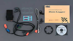
Kit Contents:
•Data logger unit •RS logger wire harness •USB cable •Front wheel speed sensor •Front wheel speed sensor stay (Same for RS125R/RS250R) •Front wheel speed sensor rotor (Same for RS125R/RS250R) •HRC Data Analyzer Software CD-ROM •Data logger unit stay (RS125R only) •Instruction manual (Japanese & English)
Measured Data:
1. Engine RPM
2. Throttle Position (%)
3. Front Wheel Speed
4. Detonation x 2 Channels (HRC Detonation Counter with output plug required)
5. Analogue Signal (0-5V) x 4 Channels
*Sampling for each item can be set from 5`300msec (detonation sampling is fixed @ 300msec)

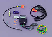
The detonation counter sensor picks up an engine's irregular combustion (detonation) and displays the number of times it occurs on the detonation counter unit. When used with the HRC Data Logger (RS125R/ 250R), the counter provides a detailed detonation map which greatly assists in carburettor setting.
Kit Contents:
•Detonation Counter•Plug Cap •Spark Plug •Sensor Assy •Detonation Counter unit stay •Rivet •Washer •Wire Harness •Sub Harness
Main Features:
Detonation Unit
•Voltage 12V
•Usable Temperature 0ÅC~60ÅC
•Counter Display Time Maintained @30 min
•Data Logger Output 5 Pulse Output (pulse width 10msec)
Sensor
•Spark Plug Washer Type
PRICE LIST
06501-NX4-731 RS125 DETONATION COUNTER KIT Discontinued - Sold Out
06501-NX5-730 RS250 DETONATION COUNTER KIT Discontinued - Sold Out
RS125 + RS250 DETONATION SENSOR WIRE ASSY Discontinued - Sold Out
06501-NX4-731 RS125 DETONATION COUNTER KIT Discontinued - Sold Out
06501-NX5-730 RS250 DETONATION COUNTER KIT Discontinued - Sold Out
RS125 + RS250 DETONATION SENSOR WIRE ASSY Discontinued - Sold Out
Click the button below for information about our replacement Detonation Sensor wire.
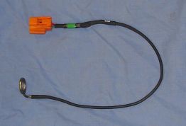
Replacement Detonation Sensor for the HONDA RS125/ RS250 HRC Detonation Counter
£175.00 + VAT
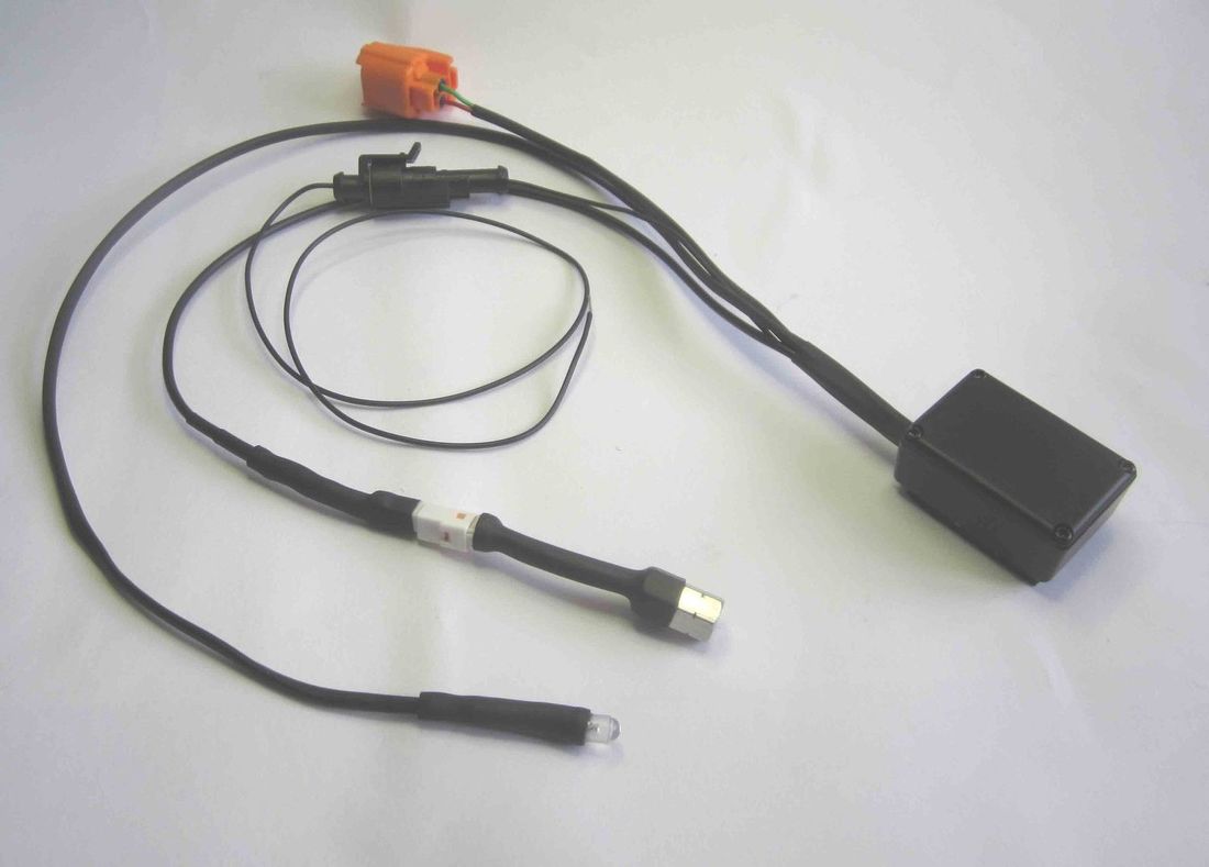
The unit provides a replacement detonation sensor for the HRC logger or HRC detonation counter and upgrades the system to add a blue flash indicator.
Plug the Orange connector into the counter or logger connection loom, replacing the existing sensor.
Wire the black wire into the black wire feeding the HRC unit.
Feed the indicator up to the dash foam, drill a 3mm hole in the foam and push the indicator through to face the rider.
£175.00 + VAT
The unit provides a replacement detonation sensor for the HRC logger or HRC detonation counter and upgrades the system to add a blue flash indicator.
Plug the Orange connector into the counter or logger connection loom, replacing the existing sensor.
Wire the black wire into the black wire feeding the HRC unit.
Feed the indicator up to the dash foam, drill a 3mm hole in the foam and push the indicator through to face the rider.
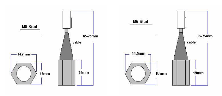
Installation Procedure for the M6/M8 stud detector
The mounting position should be on the head studs. The sensor should be tightened to the normal head nut tightness.
RS125 for the 5 stud head use the M8 sensor, 6 stud head use the M6 sensor
RS250 for the 7 stud head use the M6 sensor
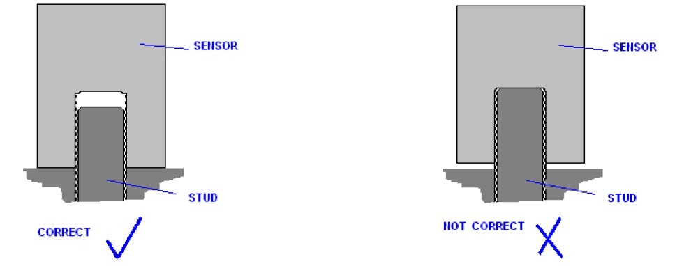
The sensors outside metal surface must make contact to the head or block or steel washer or nut. The inside surface should not touch the top of the stud. The contact of the sensor should be of high quality and clean to ensure the resonance coupling. The whole of the sensors metal surface needs to be in level contact.
M6 sensor: the detector has a maximum of 6mm of internal threads.
M8 sensor: the detector has a maximum of 8mm of internal threads.
If the threads are too long for the senor use a spacer nut or single washer
Only use a single copper washer between the head and the detector if the washer is required for the water seal such as on the standard head.
On powering up the unit will generate a detonation signal and/or flash the indicator this is normal and provides a test for the power and indicator
The detector amplifier unit must be mounted at least 80mm away from the ignition coils. Also route all detector cables away from HT leads or the coil.
The mounting position should be on the head studs. The sensor should be tightened to the normal head nut tightness.
RS125 for the 5 stud head use the M8 sensor, 6 stud head use the M6 sensor
RS250 for the 7 stud head use the M6 sensor
The sensors outside metal surface must make contact to the head or block or steel washer or nut. The inside surface should not touch the top of the stud. The contact of the sensor should be of high quality and clean to ensure the resonance coupling. The whole of the sensors metal surface needs to be in level contact.
M6 sensor: the detector has a maximum of 6mm of internal threads.
M8 sensor: the detector has a maximum of 8mm of internal threads.
If the threads are too long for the senor use a spacer nut or single washer
Only use a single copper washer between the head and the detector if the washer is required for the water seal such as on the standard head.
On powering up the unit will generate a detonation signal and/or flash the indicator this is normal and provides a test for the power and indicator
The detector amplifier unit must be mounted at least 80mm away from the ignition coils. Also route all detector cables away from HT leads or the coil.
Sensitivity Adjustment
The sensitivity adjustment is by a 15 position switch; 0 is the most sensitive and F is the least.
The sensitivity adjustment is by a 15 position switch; 0 is the most sensitive and F is the least.
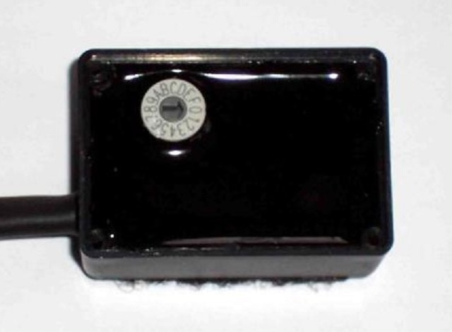
Set the sensitivity at the most sensitive = 0. This may show a continuous blue indication while running the engine in normal conditions. Then with the engine running slightly rich, reduce the sensitivity (go towards F) until the light never flashes under load with the RPM in the power band.
A typical detonation signal is shown below. If the unit is too sensitive then engine noise will be detected (shown as X), the unit needs to be set higher than that level. The range that detonation is detectable is wide (level Y).
A typical detonation signal is shown below. If the unit is too sensitive then engine noise will be detected (shown as X), the unit needs to be set higher than that level. The range that detonation is detectable is wide (level Y).
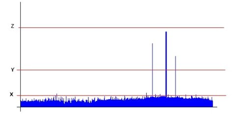
If the sensitivity is still too high then please contact the office as a suitable washer placed between the cylinder head or block with reduce the detection sensitivity
Leaded Fuel
Please Note; leaded fuel does not detonate as easily at unleaded fuels, the point of increased detonation on leaded fuel will be much leaner than the optimal fuel setting. The setting of the detonation unit will therefore be affected.
Excessive Detonation count
. The effect that the sensor detects can also be caused by mechanical bangs. Worn bearings in the crank or con rod can easily slap against the cylinder head when a higher revs.
. Interference can also cause the detector amplifier to detect non existent detonation, the cables and amplifier must be mounted away from the HT coil, HT wire or the LT coil drive wiring.
. Mid throttle (on the Needle / lean needle) detonation can cause actual detonation to occur that is not damaging to the piston but is still a detonation and will still be detected / counted.
Specifications:
Detector amplifier
Voltage range 9V to 20V
Input Current 5mA nominal 20mA peak
Sensor temperature range -10degC to +130degC
Amplifier temperature range -10degC to +60degC
Weight Approx 100g
Detonation output -40V 1mA 16uS
Led / Logger output +5V 5mA 200mS
Voltage range 9V to 20V
Input Current 5mA nominal 20mA peak
Sensor temperature range -10degC to +130degC
Amplifier temperature range -10degC to +60degC
Weight Approx 100g
Detonation output -40V 1mA 16uS
Led / Logger output +5V 5mA 200mS
Exports of all parts supplied outside of UK, to EU Countries, USA, Australia, South Africa, Asia etc are exempt from UK VAT and will be charged 0% VAT.
On arrival to your destination country, you may be asked to pay additional duties and taxes by customs, before the shipment is delivered.
Import tax, customs & duties regulations vary from country to country.
Payment of all Import tax, customs & duties charges are the responsibility of the customer.
SP125 Limited
22 Walker Wood, Baildon, Shipley, West Yorkshire, BD17 5BE, England
Telephone 01274 583231 [email protected] Mobile 07738 626165
22 Walker Wood, Baildon, Shipley, West Yorkshire, BD17 5BE, England
Telephone 01274 583231 [email protected] Mobile 07738 626165

SP125 Limited Disclaimer
Honda, HRC and all other parts supplied by the SP125 Limited are not guaranteed when used in competition events.
As such, it is a condition of our making all parts available that it is solely the decision of each individual, rider, team member or
team whether they choose to use any part supplied and in doing so, absolve the manufacturer and SP125 Limited of any or all
such claims, including damage to equipment and/or injury to personnel irrespective of how caused.
All parts remain property of SP125 Limited until paid for in full.
All 'special order' parts, that are ordered specially under the instruction of the customer, are non returnable and non refundable.
