Power-Valve controller system
RS125 / RS250 Honda
Please 'Refresh' this page every time you visit. If it is slow to reload, you know then that this page has been updated since your last visit.
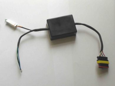
This unit allows you to control the powervalve motor, without the need of a HRC / Jha / BPS powervalve ignition.
Also it can be used to replace the now unavailable Jha Powervalve Electronic Box
Overview
The unit controls a Power Valve motor according to the RPM. The position is set by a programmed map.
The map can be loaded by software provided using the small white connector and a programming lead.
The unit can be used to upgrade an existing CDi to have Power Valve control or replace a damaged system on a RS125 or RS250.
Only one map is operational at any time.
If no map is loaded then the default map is used – See office
Un-connecting the small white connector allows the cables to be set.
Wiring
Connection to a RS250 Power Valve unit:
PV controller PV motor Action
Pin 1 Red White/Red Motor up
Pin 2 Black White/Black Motor down
Pin 3 Yellow Light Green PV feedback
Pin 4 Green Green/Blue Ground
Pin 5 White White +5V PVf supply
Connection to Taco for power and the rpm signal,
PV controller Action
Black Power
Blue Taco RPM
Green Ground
Mount the unit in the nose of the motorcycle
Mechanical Set-up
To set up the High RPM position
1. Remove the small white connector link
2. Power the electrical system up from a Battery supply
3. The motor will move to the High RPM position while no RPM or the link is still removed
As soon as RPM is detected or the link is replaced the unit will resume normal map position.
Leave the Small white connector link in place in normal operation
Specifications:
Voltage range V to 18V
Input Current 100mA + Motor Drive current nominal
Drive current 10A maximum
Temperature range -10degC to +130degC
Weight Approx 150g
RS125 Honda Powervalve Controller : £320.00 + VAT
RS250 Honda Powervalve Controller : £320.00 + VAT
Power-Valve controller Programming
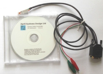
Power-Valve controller system Programming Lead & Software £30.00 + VAT
The Programming kit for the PV unit consists of a PC Software CD and programming lead
The Programming kit for the PV unit consists of a PC Software CD and programming lead
WARNING
This programming software has the ability to program the PV controller unit with unsuitable maps.
There are no upper or lower level limits or restriction on map values.
PC Connection
Find the location of a free Communication port
• Find you comm port by [right click] my computer / properties / Hardware / Device manager
• Press the [+] on ports (COM & LPT)
• Make note of the comm port number that have and is free or use a USB adaptor
Start the software
• Select port on the menu bar / choose the port
• Power up the unit
• Plug the programming lead in to the unit
• Using the red and green battery clips connect a 12V battery ( red +ve)
Check for connection
When connected the upload and download icons become active
• If no connection the select another port and then select the correct port
• If still no connection, close and restart the software
Map control
The fixed map in the unit cannot be read or written to.
If a zero map is loaded into the unit then the fixed map will be used by the unit (crossed out page icon)
Maps can be opened and saved in PV format (open and save icons)
BPS maps can be opened and the software will convert to PV values (bps icon)
Map edit
With an active map, left click to select one point this can be moved on its own left click on one point then a second point and the points between can be moved the up or down button will move the position of the points.
Clear Page
The delete page will reset the page to a zero value; if this is downloaded to the unit then the unit will operate its factory programmed map
Reference Map
Clicking the copy icon will take a copy of the current map, the map can then be altered or a new map loaded, the copied map will shown as green behind the current map.
Clicking the paste button will overwrite the current map with the copied map
Uploading / downloading
Upload and download buttons will send the data to the PV unit or read the data back
WARNING - no error checks are performed on the data, when downloading a
map, clear the map on the software and load the data back to verify it is correct.
|
Specifications:
Voltage range Input Current Drive current Temperature Range Weight |
Specifications:
9V to 18V 100mA + Motor Drive current nominal 10A maximum -10degC to +130degC Approx 150g |
Exports of all parts supplied outside of UK, to EU Countries, USA, Australia, South Africa, Asia etc are exempt from UK VAT and will be charged 0% VAT.
On arrival to your destination country, you may be asked to pay additional duties and taxes by customs, before the shipment is delivered.
Import tax, customs & duties regulations vary from country to country.
Payment of all Import tax, customs & duties charges are the responsibility of the customer.
SP125 Limited
22 Walker Wood, Baildon, Shipley, West Yorkshire, BD17 5BE, England
Telephone 01274 583231 [email protected] Mobile 07738 626165
22 Walker Wood, Baildon, Shipley, West Yorkshire, BD17 5BE, England
Telephone 01274 583231 [email protected] Mobile 07738 626165
SP125 Limited Disclaimer
Honda, HRC and all other parts supplied by the SP125 Limited are not guaranteed when used in competition events.
As such, it is a condition of our making all parts available that it is solely the decision of each individual, rider, team member or
team whether they choose to use any part supplied and in doing so, absolve the manufacturer and SP125 Limited of any or all
such claims, including damage to equipment and/or injury to personnel irrespective of how caused.
All parts remain property of SP125 Limited until paid for in full.
All 'special order' parts, that are ordered specially under the instruction of the customer, are non returnable and non refundable.


