Detonation Detection System for HONDA RS125/ RS250
Please 'Refresh' this page every time you visit. If it is slow to reload, you know then that this page has been updated since your last visit.
Detonation Detection System for HONDA RS125/ RS250
This system is optimized for Honda RS125 / RS250 and any other single or twin cylinder 2-stroke engine
Detonation detection system
M8 and M6 Stud detector
Overview
Detonation is the pre-ignition of fuel in the cylinder and can cause piston damage; a certain level of detonation is good (fuel dependent) to ensure that the engine is running at the optimal level. The detection system allows detonation to be detected and a bright indicator flash indicates a detonation has occurred to warn the rider/driver. The number of detonations on 1 or 2 cylinders can be displayed if the counter is connected.
The Detonation Detection System allows a plug together system that can be simply expanded from a simple single cylinder system to a full dual cylinder system and to other data recording/logging systems.
System variations:
Systems are built from the basic components of:
Sensor and Amplifier
Power and indicator lead
Counter unit
The power / data lead can be wire ended or have a connector for datalogger
M8 and M6 Stud detector
- Simple to add to your engine – no special long reach spark plug required
- Fits on the cylinder head M6 or M8 Cylinder Head Stud stud head
- Low cost sensor replacement
- Set of the level of detonation or pre-detonation you want to monitor
- Small 45mm x 32mm x 15mm amplifier box
- Expandable to add a counter, output to logger
- Option for direct connector into HRC counter or Logger
Overview
Detonation is the pre-ignition of fuel in the cylinder and can cause piston damage; a certain level of detonation is good (fuel dependent) to ensure that the engine is running at the optimal level. The detection system allows detonation to be detected and a bright indicator flash indicates a detonation has occurred to warn the rider/driver. The number of detonations on 1 or 2 cylinders can be displayed if the counter is connected.
The Detonation Detection System allows a plug together system that can be simply expanded from a simple single cylinder system to a full dual cylinder system and to other data recording/logging systems.
System variations:
Systems are built from the basic components of:
Sensor and Amplifier
Power and indicator lead
Counter unit
The power / data lead can be wire ended or have a connector for datalogger
|
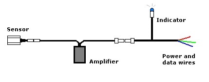
Single Cylinder : Simple detonation detection
£170.00 + VAT 1 detonation detector 1 power lead and blue indicator flash |
|
|
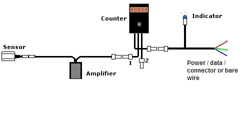
Single Cylinder : Detonation detection and counter
£300 + VAT 1 detonation detector 1 power lead and blue indicator flash 1 detonation counter |
|
|
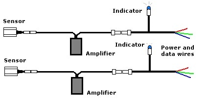
Twin Cylinder : Simple detonation detection
£340.00 + VAT 2 off detonation detector 2 off power lead and blue indicator flash |
|
|
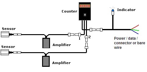
Twin Cylinder : Detonation detection and counter
£420.00 + VAT 2 off detonation detector 1 off power lead and blue indicator flash 1 off detonation counter |
|
|
Stud Detector Unit
Amplifier Unit 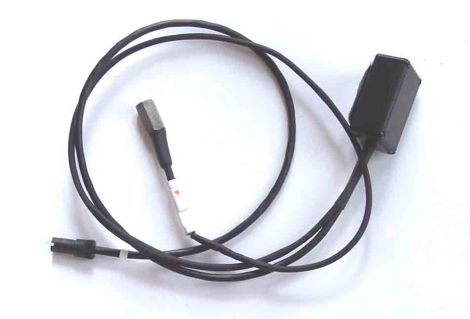
|
M6 & M8 Stud Detectors 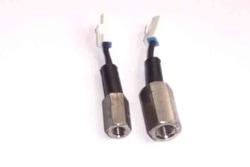
|
The detector system compromises of: a M8 or M6 Stud detector sensor and a small amplifier unit.
The sensor detects head (or block) deformation and passes this signal to the amplifier.
The amplifier produces two output signals:
(A) A standard detonation profiled pulse
(B) An indicator drive for the blue indicator or data logger
The (A) output can be coupled to other type of detonation detection systems such as:
Honda detonation counter and logger
BPS CDi ignition and engine control systems
Cougar Data Recording motorcycle logging system
The (B) output can be coupled to loggers with standard 5V analogue or digital inputs
Aim MyChron Extreme system
If connection to one of the above is required then request a power cable with a logger output connection.
Note that the BPS/cougar cylinder pressure cannot be measured by this type of sensor
On powering up the unit will generate a detonation signal and/or flash the indicator this is normal and provides a test for the power and indicator
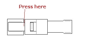
Sensor fitting
1. To disconnect the White JST connector, push with fingernail at the join
The sensor detects head (or block) deformation and passes this signal to the amplifier.
The amplifier produces two output signals:
(A) A standard detonation profiled pulse
(B) An indicator drive for the blue indicator or data logger
The (A) output can be coupled to other type of detonation detection systems such as:
Honda detonation counter and logger
BPS CDi ignition and engine control systems
Cougar Data Recording motorcycle logging system
The (B) output can be coupled to loggers with standard 5V analogue or digital inputs
Aim MyChron Extreme system
If connection to one of the above is required then request a power cable with a logger output connection.
Note that the BPS/cougar cylinder pressure cannot be measured by this type of sensor
On powering up the unit will generate a detonation signal and/or flash the indicator this is normal and provides a test for the power and indicator
Sensor fitting
1. To disconnect the White JST connector, push with fingernail at the join
2. When positioning the sensor cable, heat the sensor lead to soften and mold to the required position
Options: . Longer cables on the amplifier for Karts are optional, this allow the counter and/or the blue indicator flash to be mounted at the front / steering wheel
Connections to loggers … please contact office for details / options available
Options: . Longer cables on the amplifier for Karts are optional, this allow the counter and/or the blue indicator flash to be mounted at the front / steering wheel
Connections to loggers … please contact office for details / options available
Counter Unit
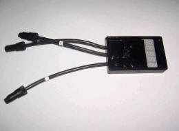
The counter unit (for single or dual cylinder) has two detonation detector inputs labelled (1) and (2) and a power connection.
The detector amplifier/s can then be powered via the counter unit.
. The count values are stored in a non-volatile memory and so are unaffected by having the power removed.
. The value normally displayed is the addition of cylinder 1 and cylinder 2 count values
. Pressing the button briefly once will cycle through the count values
The display will show ….
1=
{Cylinder 1 count value}
2=
{Cylinder 2 count value}
Total
{Addition of cylinder 1 and 2} the normal display
. When cycling through the cylinder counts the counter system will continue to count any detonations
. 20 seconds after a button is pressed the display will fade to reduce power consumption
Throttle connection
On the power and indicator lead connect the yellow/blue wire to the engines throttle , 0-5V input
Reset and throttle monitor
. To reset all the values to zero: press and hold the button for 2 seconds
. After 2 seconds the display will show the throttle position to test the connection and ensure the full throttle range is displayed
Throttle voltage Area Display
< 1.35V Low throttle ^____
1.35V – 2.24V Low mid _^___
2.24V – 3.00V Mid __^__
3.00V – 4.00V Upper Mid ___^_
>4V Full ____^
Throttle graph
. The throttle graph gives a display of detonation counts for each of the five throttle position areas
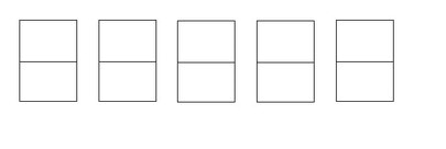
75% to 100% of the maximum number of detonations are indicated by a circle at the top of the display
50% - 75% maximum is a line at the top of the display
25% - 50% maximum is a line in the middle
<25% the maximum is a line at the bottom
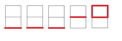
Examples :
1. Most detonation is on the main jet at full throttle, 25-50% of that maximum is spread over the needle drive area – an even set-up
50% - 75% maximum is a line at the top of the display
25% - 50% maximum is a line in the middle
<25% the maximum is a line at the bottom
Examples :
1. Most detonation is on the main jet at full throttle, 25-50% of that maximum is spread over the needle drive area – an even set-up
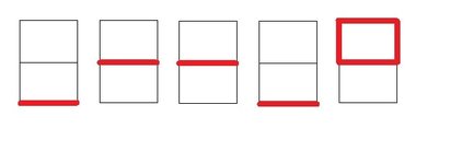
2. Most detonation is on the needle perhaps too lean in this area
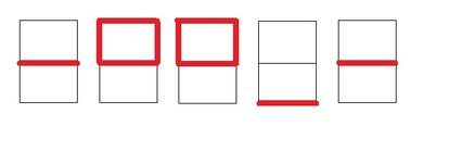
3. All the detonation is on the main jet Datalogger connection
Datalogger connection
. The counter power cable has an indicator output that flashes for either cylinder (1) or cylinder (2).
This line can be used for a single logger channel.
The data output connector allows a logger to be easily connected
. The data output connector:
Pin 1 red = power
Pin 2 yellow = cylinder (1) 0-5V data
Pin 3 blue = cylinder (2) 0-5V data
Pin 4 green = gnd
. The Yellow and blue data lines can be joined if only one channel on the logger is available
. The unit can be power from the data output connector if required
. The unit has a Velcro mounting pad
Reading the count on generator only powered engines
The count values on the counter are retained even without power connected to read on a generator only motorcycle then build a small 9 to 14V battery ( 500mAH or above ) with a connector and power the motorcycle for the short period required to read the display.
For non power circuit motorcycles
If no power in use is available then use a rechargeable 250mAh PP3 battery and a PP3 holder wired into the power lines, this will power a detonation system (single and twin with or without counter ) for over 2 hours.
Installation Procedure for the M6/M8 stud detector
The mounting position should be on the head bolts or as central as possible and in the top half of the engine. The sensor should be tightened to the normal head nut tightness
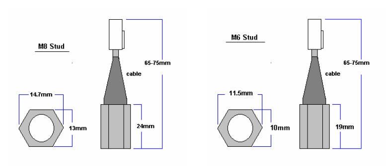
For the M6 : Use an M6 head bolt or stud, the detector has a maximum of 6mm of internal threads until the head of the internal set screw.
For the M8 : Use an M8 head bolt or stud, the detector has a maximum of 8mm of internal threads until the head of the internal set screw.
The mounting position should be on the head bolts or as central as possible and in the top half of the engine. The sensor should be tightened to the normal head nut tightness
For the M6 : Use an M6 head bolt or stud, the detector has a maximum of 6mm of internal threads until the head of the internal set screw.
For the M8 : Use an M8 head bolt or stud, the detector has a maximum of 8mm of internal threads until the head of the internal set screw.
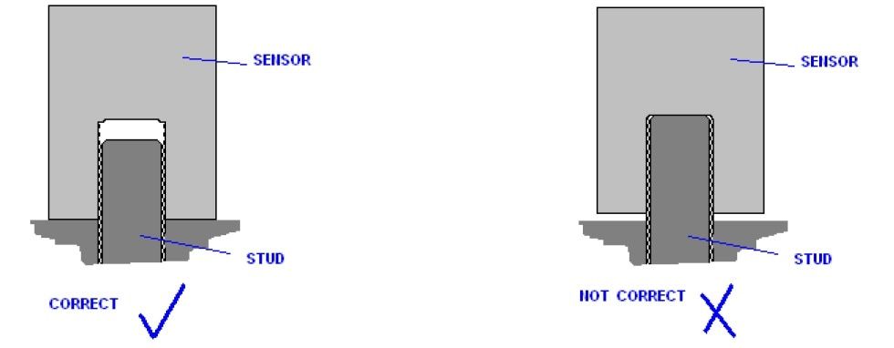
The sensors outside metal surface must make contact to the head or block or steel washer or nut.
The inside surface should not touch the top of the stud. The contact of the sensor should be of high quality and clean to ensure the resonance coupling.
The whole of the sensors metal surface needs to be in level contact.
Only use a copper washer between the head and the detector if the washer is required for the water seal such as on a Honda RS125 and Honda RS250, this will require adjustment to the sensitivity of the detection.
If the sensor cable is in a tight location use a heat-gun to warm the heat-shrink and bend the cable to an angle
The detector amplifier unit must be mounted at least 80mm away from the ignition coils.
Also route all detector cables away from HT leads or the coil.
Honda Power connectionsWire behind the tachometer:
Red positive power to Honda black
Green Chassis to Honda green
Yamaha Power connectionsWire behind the tachometer:
Red positive power to Yamaha Brown
Green Chassis to Yamaha Black
If connecting the unit to an AIM MyChron extreme then the power connection can be via the signal connector
NOTE :
. Mount the blue indicator in the dash foam pointing towards the rider.
. Velcro mount the detector amplifier unit to the inside of the chassis: DO NOT MOUNT ON THE SIDE OF THE COIL.
. Ensure all cables are away from the HT leads, if the HT lead goes right route the detonation lead left.
. Velcro mount the counter unit in a visible position and ensure that the button cannot be pressed accidentally or pushed by other cables.
. Use the coloured tie-wraps to indicate which cylinder is which; red=1, blue=2 ensure that the leads are in the correct connectors for cylinders.
Sensitivity Adjustment
The sensitivity adjustment is by a 15 position switch; 0 is the most sensitive and F is the least.

|
|
If there is no data for your engine on the sensitivity level required, set the sensitivity at the most sensitive = 0.
This will no doubt show a continuous blue indication while running the engine in normal conditions.
Then with the engine running slightly rich, reduce the sensitivity until the light never flashes under load with the RPM in the power band.
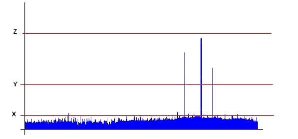
A typical detonation signal is shown below.
If the unit is too sensitive then engine noise will be detected (shown as X), the unit needs to be set higher than that level. The range that detonation is detectable is wide (level Y).
This will no doubt show a continuous blue indication while running the engine in normal conditions.
Then with the engine running slightly rich, reduce the sensitivity until the light never flashes under load with the RPM in the power band.
A typical detonation signal is shown below.
If the unit is too sensitive then engine noise will be detected (shown as X), the unit needs to be set higher than that level. The range that detonation is detectable is wide (level Y).
If the sensitivity is still too high then please contact the office as a suitable washer placed between the cylinder head or block with reduce the detection sensitivity.
Leaded Fuel
Please Note; leaded fuel does not detonate as easily at unleaded fuels, the point of increased detonation on leaded fuel will be much leaner than the optimal fuel setting. The setting of the detonation unit will therefore be affected.
Excessive Detonation count
. The effect that the sensor detects can also be caused by mechanical bangs. Worn bearings in the crank or con rod can easily slap against the cylinder head when a higher revs.
. Interference can also cause the detector amplifier to detect non existent detonation, the cables and amplifier must be mounted away from the HT coil, HT wire or the LT coil drive wiring.
. Mid throttle (on the Needle / lean needle) detonation can cause actual detonation to occur that is not damaging to the piston but is still a detonation and will still be detected / counted.
Detonation system simple test
With no counter :
Power up system – check for short flash on power up
No flash – Check 4 way binder connections and power feed
Disconnect sensor from engine, plug back into system, Unscrew lid of box and set sensitivity to 0 – check arrow points to zero.
With system powered up, hold sensor loosely in hand.
Tap end of sensor with the flat of a new 15-17mm spanner so that a crisp audible ‘tink’ can be heard
With counter :
Power up system – check for short flash on power up
No flash, No count display – Check 4 way binder connections and power feed
Flash No display – Send counter for testing, test each sensor as above
Disconnect the counter and plug each sensor amplifier into the power lead and test as above
Specifications:
Sensor
Sensor temperature range -20degC to +150degC
Connector JST IP65
Detector amplifier
Voltage range 9V to 20V
Input Current 5mA nominal 20mA peak
Amplifier temperature range -10degC to +90degC
Size 46mm x 32mm, 20mm high
Weight Approx 100g
Water ingress Washable with cover on
Mounting Industrial Velcro
Connectors JST / Binder 719
Detonation output -40V 1mA 16uS
Led / Logger output +5V 5mA 200mS
Counter
Voltage range 9V to 20V
Input Current 50mA nominal 150mA peak
Temperature range -10degC to +60degC
Size 72mm x 45mm , 15mm high
Weight Approx 60g
Water ingress Washable
Mounting Industrial Velcro
Connectors Binder 719
Inputs 2 off –40V 16uS piezo
Led output +5V 5mA 200mS
Memory 3 not power dependent, (1),(2), (1)+(2)
Max count 99999
Exports of all parts supplied outside of UK, to EU Countries, USA, Australia, South Africa, Asia etc are exempt from UK VAT and will be charged 0% VAT.
On arrival to your destination country, you may be asked to pay additional duties and taxes by customs, before the shipment is delivered.
Import tax, customs & duties regulations vary from country to country.
Payment of all Import tax, customs & duties charges are the responsibility of the customer.
SP125 Limited
22 Walker Wood, Baildon, Shipley, West Yorkshire, BD17 5BE, England
Telephone 01274 583231 [email protected] Mobile 07738 626165
22 Walker Wood, Baildon, Shipley, West Yorkshire, BD17 5BE, England
Telephone 01274 583231 [email protected] Mobile 07738 626165

SP125 Limited Disclaimer
Honda, HRC and all other parts supplied by the SP125 Limited are not guaranteed when used in competition events.
As such, it is a condition of our making all parts available that it is solely the decision of each individual, rider, team member or
team whether they choose to use any part supplied and in doing so, absolve the manufacturer and SP125 Limited of any or all
such claims, including damage to equipment and/or injury to personnel irrespective of how caused.
All parts remain property of SP125 Limited until paid for in full.
All 'special order' parts, that are ordered specially under the instruction of the customer, are non returnable and non refundable.
